


About Us
Executive Editor:Publishing house "Academy of Natural History"
Editorial Board:
Asgarov S. (Azerbaijan), Alakbarov M. (Azerbaijan), Aliev Z. (Azerbaijan), Babayev N. (Uzbekistan), Chiladze G. (Georgia), Datskovsky I. (Israel), Garbuz I. (Moldova), Gleizer S. (Germany), Ershina A. (Kazakhstan), Kobzev D. (Switzerland), Kohl O. (Germany), Ktshanyan M. (Armenia), Lande D. (Ukraine), Ledvanov M. (Russia), Makats V. (Ukraine), Miletic L. (Serbia), Moskovkin V. (Ukraine), Murzagaliyeva A. (Kazakhstan), Novikov A. (Ukraine), Rahimov R. (Uzbekistan), Romanchuk A. (Ukraine), Shamshiev B. (Kyrgyzstan), Usheva M. (Bulgaria), Vasileva M. (Bulgar).


Teaching science
 PDF
PDFThis paper describes the experience of using LabVIEW graphical programming environment created by the example of the device "voltage-to-frequency converter" and opening up to the possibility of organizing the learning process of future engineers.
Keywords: virtual laboratory, virtual instrument, LabVIEW, virtual voltage converter
One of the most important components of engineering education is the application of theoretical knowledges in practice, which is realized in on experiments, the complex laboratory works or practical trainings in high school. However, there is the problem of limited access of students to the most interesting and unique technical equipment or facilities, or the material-technical base of some universities still do not fully satisfy the need for the formation of practical skills for future professional careers of future specialists. But information technology brought measuring equipment on a completely different level, allowing quickly and inexpensively develop information-measuring devices and systems of different complexity. Therefore, their use in the learning process becomes relevant and necessary, leads to the expansion of methods and forms of education.
Today, traditional forms of laboratory workshop complemented by a virtual laboratory using the technology of simulation mathematical modeling of experiment involving hardware and software (technical) tools, computer graphics , and animation to achieve of effective interactive interaction user with the simulation environment [1,2].As a result of the use of virtual models, we obtain the following main features: high-quality preparation of students to carry out laboratory works and work with the equipment; the possibility of in-depth study of student events in the measurement systems in the design of models of systems and devices; the ability to prepare students for the corresponding courses, solving real problems.
Thus, educational virtual laboratory is a complete software product for using of modern concepts of design of large software systems, aimed at improving the efficiency of automated designing.
Among the many software products, Laboratory Virtual Instrumentation Engineering Workbench (LabVIEW), as one of the leading products of National Instruments, in our opinion is the most worthy to solve engineering problems; this application is the development of custom applications. Implementation of programs in LabVIEW called virtual appliances, or virtual instruments, because their external graphical representation and the method of operation can simulate work of the real physical devices, or equipment. Used in LabVIEW virtual instrument concept allows to create complex system of information processing which using the isolated blocks, some unique subprogrammes, virtual instruments, working with the flow of information. With educational and practical point of view, the main advantages of LabVIEW are the possibility of combining the computer simulation technology, virtual management, and natural data collection. [3] All of these possibilities provide a good reason for inclusion of LabVIEW to student training of the natural sciences and technical specialties of high school.
Therefore, the aim of our research is to create a LABVIEW application, i.e. a virtual instrument based on software environment LABVIEW, as an example of the using of LABVIEW and development laboratory facilities on it is based in high school.
The Kazakh Agro Technical University S.Seifullin on faculty "Radio Engineering, Electronics and Telecommunications" (Kazakhstan) has a long experience in research and practical work with the software and hardware complex of National Instruments LabVIEW in teaching disciplines "Computer simulation of wireless devices," "Electronics and circuit design of analog electronic devices" etc. As an example, using environment LabVIEW, i.e. an instrument, an appliance, which we need to create virtually, was taken voltage converter to the frequency. The study features LabVIEW environment and create the device we used scientific methods and techniques as the analysis, analogy, modeling, and experiment.
Having studied the potential LabVIEW environment, we have created a virtual instrument. We describe a block created diagram of the laboratory stand and algorithm of functioning of the virtual converter of voltage to the frequency. Figure 1 shows the appearance of the interface lab, developed in LabVIEW 2013 software package, describing the actions of a converter of voltage to the frequency.
The converter is controlled by the three control elements: Vin regulator that controls the input voltage of the voltage converter to the frequency; controller RC, respondent for the time constant of the integrator; Vref knob, is responsible for the reference voltage of the comparator. Also there is a "stop" button stops the simulation on the front panel.
Waveform Chart monostable multivibrator (red, upper) graphic display shows two signals: the signal on the circuit output (white, lower) and the output Figure 2 is a block diagram of a voltage-to-frequency converter. The block diagram is the source of our entire virtual instrument. For the most complete understanding of the scheme, we consider the function of the voltage converter to the frequency.

Figure1 Interface of laboratory stand
The first block of the functional diagram is input of signal. In LabVIEW, this function is performed by the Numeric Control terminal from Numeric subpalettes entitled Vin. This element can be considered as the input and output port of the block diagram or as a source and a data sink. The data are entered into the control Vin out from the front panel and fed to the block diagram by terminal Vin. Then, terminal data is sent to the Select element through a conductor.
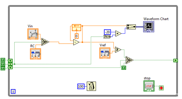
Figure 2 Block diagram of LabVIEW
The next block in the function chart is the key. A block Select executes of this feature in LabVIEW subpalettes Comparison. (Figure 3)
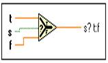
Figure 3 The electronic key
This is the basic tool of development. Select output returns to the input signal from "t" or "f" to "s" depending on the input signal. If s - true, it is connected to the output signal t, if s - a lie, it is connected to the output signal f. From block diagram it can be seen that this function is used twice.
Further, the functional diagram is an integrator. In LabVIEW, the integrator is made up of several blocks: Substract Function, Feedback Node and RC. Substract Function - This unit calculates the difference between the input values. If you connect two waves of two types of dynamic data to this function, the two terminals will be: input and output errors. Subtracting the timestamps generated numeric value (time difference) and the difference value of the numerical value of the timestamp provides a time stamp. We cannot deduct the value of the time stamp with a numeric value. Dimensions of two matrices, to subtract must be identical. Otherwise, this function returns an empty matrix. Connection panel displays the default data types for this polymorphic function.
Feedback Node - is the feedback node, which automatically appears in a While or For loops when connecting field of data output VI subroutines, functions or subroutines group VIs and functions with the field of data entry of the same VP subroutines, functions, or their groups. Feedback node stores any type of data upon completion of the current iteration, and transmits these values ??to the next iteration. Using feedback nodes avoids the large amounts of data conductors and connections. You can place a feedback node inside a While Loop or For, by selecting the Feedback Node in the Structures palette. When placed on the feedback node to branch data conductor that transmits data to an output terminal loop, feedback node transmits the values ??to the output terminal cycle. When placed on the feedback node after branching conductor, transmitting data to an output terminal loop, feedback node will transmit all the values ??back to the input field data VIs or functions, and then will give the last value at the output terminal loop.
RC - is another Numeric Control. It performs the function of the installation for the integrator time constant, i.e., it replaces the RC circuit. Together these three blocks form a chain integrator. The signal at its output grows at a constant non-zero value of signal on the input.
Then the signal from the integrator is sent to the comparator circuit. To compare the signal with a reference voltage using a function of the Greater or Equal Comparison palette. The functions Greater or Equal? (Greater than or equal to) take on any type of input data, except the complex, paths and reference numbers (refnum) and provided evidence that both inputs have the same type. We can compare numbers, strings, Boolean values, arrays, strings, clusters of numbers, clusters of lines, etc. However, you cannot compare the number with a string or a string to a Boolean value, etc. When the value on its output of the comparator input is greater than or equal to the reference voltage is set Boolean value - true. Otherwise, the output is set - a false.
The signal from the comparator is sent to the Select block input described above. In this case Select block in conjunction with the shift registers implements the functions of monostable or monostable multivibrator. The shift register stores for one-cycle output value Select. Shift registers are used when operating cycles to pass values ??from the current loop iteration to the next. Shift registers are similar to static variables in text programming languages. They look like a pair of terminals, shown at left. They are located directly opposite each other on opposite vertical sides of the loop border. The right terminal contains an arrow "up" and stores data on the completion of the current iteration. LabVIEW transmits data from the register in the next iteration cycle. The shift register is created by right-clicking on the loop border and selecting from the context menu item Add Shift Register. The shift register transfers the data of any type; it automatically adopts the first type of data it received. The data transmitted to the terminals of the shift register must be of the same type.
To initialize the shift register, you must pass on its left terminal to any value outside the loop. If not initialize the shift register, it uses the value stored in the register during the last cycle of execution, or a value used by default for the data type, if the loop is never executed. Cycle with uninitialized shift register is used when you run a VI repeatedly to assign the output value of the shift register values ??are taken from the last execution of the VI. To save state information between subsequent launches of the VI, should be left to the left terminal of the shift register input is not defined. After completion of the last cycle, the value written in the register will be at the right terminal. During the subsequent data transfer cycle from the terminal through the right it will be transferred latest value written in the register. You can create multiple shift registers in a single cycle structure. If in one cycle is performed several operations use a shift register with a plurality of terminals for storing data obtained as a result of various cycle operations. Как описывалось выше, ранее цикл может быть остановлен при нажатии кнопки «стоп».
Thus, the designed virtual appliance is the voltage converter to the frequency of and guidance on the implementation of laboratory work in order to study its working principle, it allows you to explore the work of the virtual voltage converter to the frequency and increase the level of knowledges for understanding the functioning of the physical processes in the field of graphical programming.
Nevertheless, any high VI, in most cases, no substitutes for a teaching its action exerted on the student, working with real equipment. It is aware of, and the students themselves, as evidenced by the results of the survey conducted at the Department of "Radio Engineering, Electronics and Telecommunications" within the VI validation experiment on the subject "Electronics and circuit design of analog electronic devices". In general, giving a positive assessment of the new VI (84% respondents), 54% of students surveyed said that they believe the work with the real laboratory equipment more useful compared to virtual labs and at the same time pointed out that information technology training penetrating all the wider area, including in the area of ??engineering education and professional activity of teachers [5].
Today, there is an urgent need of enterprises for qualified specialists, able to create and maintain a modern management system. Substantial assistance in the solution of these problems could have young professionals who have studied the LabVIEW software package in higher education. Experienced professionals with experience often can not effectively make full use of the opportunities offered by modern systems, this requires additional knowledge that you can get on training courses. The proposed approach to the construction of laboratory facilities aimed at increasing the level of theoretical knowledges and practical skills of students and creative, or creative thinking.
In future we will plan gradually to develop a new computer lab works on other technical subjects, and to involve students in research that will enable more efficiently to use of LabView programming environment and to develop laboratory facilities with the active participation of students.
2. Egorov E.N., Rempen I.S. Application of Multisim software application package for radio physical circuit simulation, 2008, 24 p. - URL: http://www.sgu.ru/files/ nodes/30844/ MULTISIM. Pdf (reference date 25/01/2016).
3. Kretov V., Kukushin A.V., Perepelovsky V.V., Shapovalov V.I. Scientific and educational technology in an environment of virtual instruments. Machinery and microelectronics technology. Exhibition ETU - "LETI" 24.03.2003./Base of programming, data collection, processing and management in an integrated LabVIEW environment. - URL: http: //www.etu.ru/kafedrs/fet_eips/acni/lab_l.htm (reference date 25/01/2016).
4. Herniter Mark E. Multisim®7: The modern system of computer modeling and analysis of circuits of electronic devices. (Trans. from English.)/Per. from English. Osipov A.I. - M.: Publishing house DMKPress, 2006.-488p.
5. Khamzina B.E. Organization of professional activity in the preparation of teachers to use ICT tools // International journal of experimental education. - 2014. - №5 (1). - P.85-90.
Khamzina B., Nauryz K. CREATING OF LABVIEW APPLICATIONS. International Journal Of Applied And Fundamental Research. – 2016. – № 6 –
URL: www.science-sd.com/468-25133 (08.01.2026).