


About Us
Executive Editor:Publishing house "Academy of Natural History"
Editorial Board:
Asgarov S. (Azerbaijan), Alakbarov M. (Azerbaijan), Aliev Z. (Azerbaijan), Babayev N. (Uzbekistan), Chiladze G. (Georgia), Datskovsky I. (Israel), Garbuz I. (Moldova), Gleizer S. (Germany), Ershina A. (Kazakhstan), Kobzev D. (Switzerland), Kohl O. (Germany), Ktshanyan M. (Armenia), Lande D. (Ukraine), Ledvanov M. (Russia), Makats V. (Ukraine), Miletic L. (Serbia), Moskovkin V. (Ukraine), Murzagaliyeva A. (Kazakhstan), Novikov A. (Ukraine), Rahimov R. (Uzbekistan), Romanchuk A. (Ukraine), Shamshiev B. (Kyrgyzstan), Usheva M. (Bulgaria), Vasileva M. (Bulgar).


 PDF
p. 11-15
PDF
p. 11-15
The wave and friction resistance calculations methods, which are the main part of the total resistance of a moving ship, have been developed. The wave resistance is defined by using Michell's integral and the friction resistance is calculated by using the integral relation for curved surfaces. All these calculations give the possibility to take into account the hull form influence upon its resistance. The vortex resistance, having connected with the bow, shock, and breaking waves, also with the boundary layer separation, still can not be calculated.
So, the carried out research has shown that on those Froude numbers, on which the wave resistance is the main part of the residual resistance, it is possible to use the main part of Michell's integral for its definition [1]. It is necessary to take into account that Michell's integral defines only the resistance, which is tied to the bow and stern Kelvin waves systems, because Michell found his solution to ideal fluid.
For the practical calculation of wave resistance a special form of Michell's integral [2] on an analytical grid theoretical drawing is used. What we have called the analytical grid, are ship lines, the equations of which have been described by the ship versiera equation.
To calculate the friction resistance of the given hull shape the integral relation is used, specially obtained for curved surfaces [3] and the analytical grid too.
Analytical grid
In the general case, it is quite impossible to obtain the equation of the given ship hull surface, however it is quite necessary to have not only the ordinates of each point of the hull surface, but the derivatives in them for the computing of wave resistance and friction resistance. To solve such tasks it is necessary to describe the frames and waterlines by equations, in order to use an analytical grid instead of the surface equation
So, we use the graphic representations in the EXCEL program and the calculations in the FORTRAN program for obtaining the analytical grid of the theoretical drawing. The waterlines and the frames are built by the offset in the EXCEL program, as it has been shown in Fig. 1. They are obtained coordinated, because the frames and the waterlines are intersected at the same points of the surface. So, by using the FORTRAN program, we have each frame and each waterline approximated by the ship versiera equation.
![]() (1)
(1)
The approximation and, consequently, the coordinating can be obtained with the desired and the given accuracy. The accuracy is defined by the ordinates and by the drawing, as all, even the insignificant irregularities are seen on the drawings in the EXCEL program.
The ship versiera (1) are calculated by the least squares method. The analytical grid, which is built by the approximated frames and the waterlines is shown in Fig. 1 (here the true proportions are not practically observed). Thus, the approximation process is the most laborious part of the computations. The initial and the approximated frames of the vessel «Rodina» are shown in Fig. 2. As the presented lines are being merged together, the calculated curves are marked by the dots.
Calculation of the wave resistance of ships.The special form of Michell's integral with the separation of the main (nonoscillatory) part and the part, which reflects the bow and stern Kelvin waves systems interaction, has been described in the paper [2]. The calculations by using this form can be easily carried out, when the hull surface equation is given analytically in the form of y = f1(x)·f2(z), but for a ship's hull theoretical drawing given by offsets it is required to work out a special algorithm.
It is possible to carry out only if we know the higher-order derivatives in the waterlines' ends. However we had to carry out a number of the preliminary researches. We had to find out the minimum number of frames and waterlines, for which the necessary accuracy can be reached. In addition, it was quite necessary to decide the question on the derivatives' highest order, having being entered into the Michell's integral computation.
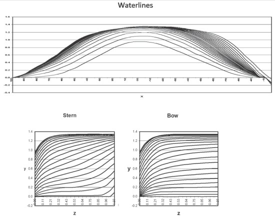
Fig. 1. Bony plans under the main waterline of Todd's model is EXCEL
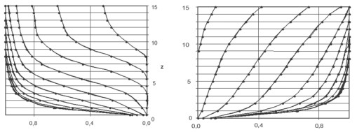
Fig. 2. Comparison of the calculated and original frames
The fact is that the waterlines' equation is given in implicit form (1). In this case, it is possible to obtain any order's derivatives up to infinity. To find the sufficient order of derivatives for accurate calculation we have carried out the calculation taking into account the derivatives from the 8th to the 16th order. So, has been found, that it is quite sufficient to perform the calculations with derivatives up to the 16th order.
The second challenge is connected to integration with respect to z, as the calculation is carried out by using the analytical grid instead the equation.
In this case, we had to perform the integration over the whole hull's surface by the special formula, received after its integration by the parts.
To check the precision of the calculation the experimental curves of three different models have been used: Todd's models of the 60th series and the two models of the river vessels «Sevan» and «Rodina». The experimental curves of the wave and the residual resistance of Todd's model have been obtained in different years and in different towing tanks of the world [4].The experimental data of the river vessels has been obtained in the GIEWT tank [5]. Thus, the calculated and experimental curves are shown in Fig. 3, 4 and 5.
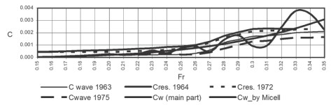
Fig. 3. Calculated and experimental coefficients of the wave and the residual resistance of Todd's model
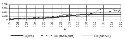
Fig. 4. Calculated and experimental coefficients of the wave resistance of model «Sevan»
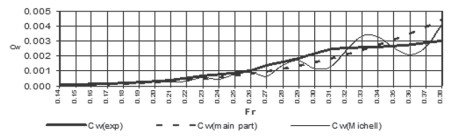
Fig. 5. Calculated and experimental of the wave resistance coefficients of model «Rodina»
One can see in Fig. 3 that the calculated and experimental wave resistance curves coincide up to the 0,22 Froude number, but at the higher Froude numbers - it approaches residual resistance curves. This is due to the fact that the wave resistance is low at the small Froude numbers, but it is the main part of the residual resistance at the higher Froude numbers.
It is seen from these curves that this method of wave resistance calculation can be used in the designing process of a theoretical drawing of any displacement ships.
Calculation of friction resistance
The friction drag design of the vessels' displacement tons is usually defined by the friction extrapolators with sufficient accuracy. But in this case, the calculations are fulfilled only on the wetted surface area, the hull shape is not taken into consideration.
If the friction resistance is defined by the integral relation, then the hull form is taken into account, and there is the possibility to trace the tangential stresses distribution on the wetted surface, and we can even define the location of the boundary layer separation. The development of the integral relation for the ship hull shape is given in the book [3], therefore here is not shown.
The needed velocity field is fulfilled by using the Hess - Smith program. In this case the velocity field is computed on the whole underwater part with the exception of the flat bottom. Therefore the calculated resistance of Todd's and «Rodina» models is equal to the sum of the resistance of curvilinear hull sides and the resistance of a flat bottom, which is defined with help of a friction extrapolator.
The Weinblum 1100 model's hull form is symmetrical about the midsection, and is slenderer to the aft and stern ends. This model does not have a flat bottom. The Weinblum model's hull surface has been described by an equation, therefore one has a possibility to check the validity of this suggested method for the calculation of friction resistance by the integral relation using this model. The comparison of the results of the calculations obtained by the integral relation and by the friction extrapolator are given in Fig. 6 and 7.
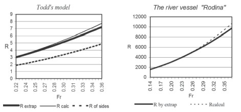
Fig. 6. Friction resistance curves obtained by extrapolator and by the integral relation of Todd's model and of river vessel «Rodina»
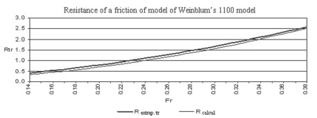
Fig. 7. Friction resistance curves obtained by extrapolator and by the integral relation
of Weinblum's 1100 model
Conclusions
The methods of the calculation of wave and friction resistance for the displacement ships, the theoretical drawing of which is given by the offset sheets, have been developed. Such calculations permit to evaluate the ship hull resistance at all the designing stages without labour-consuming and expensive towing tests. So, this method distinguished that all the design stages are quite available for performing them in the design process of the theoretical drawing in the ship-designing department.
To fulfill the calculations of resistance the method of the analytical grid of hull shapes practically substituting the equation of surface hull, which cannot be obtained for any ship hull form has been developed.
The analytical grid allows us to receive ordinates of a theoretical drawing and derivatives of any order in each point of its surface, that opens possibilities not only for given calculations, but also for various research in the field of ship hydrodynamics.
It should be noted that the used ship's versiera's significance for the approximation of the thoretical drawing cross section. There is no other curve, which can allow with such accuracy to approximate the lines of hull surface. The approximation could not be carried out with the required and the given accuracy without this curve, and, consequently, the present calculations could not be performed.
It is necessary to mark also the large possibilities of EXCEL, permitting us to receive the table of ordinates of sections of a theoretical drawing. The possibility to transpose in EXCEL a matrix of data and approximated data considerably facilitates labour-consuming work of approximation and coordination of a lines drawing. These possibilities considerably reduce the colossal work of deriving an analytical grid with a great many frames and waterlines.
1. Gotman A.Sh. Definition of wave resistance and optimisation of contours of courts. - Novosibirsk: NGAVT, 1995.
2. Gotman A.Sh. Study of Michell's Integral and Influence of Viscosity and Ship Hull Form on Wave Resistance. // «Ocean Engineering International», 2002, 8, No 2, 74 - 115;
3. Gotman A.Sh. Designing of contours of courts with a developed covering. - Leningrad (St.-Petersburg): «Shipbuilding», 1979.
4. Proc. of the Workshop on Ship Wave Resistance Computations - David W. Taylor, «Naval Research and Development Center, Bethesda, Maryland». The Overview of Results by Kwang June Bai, Part of Series 60 Block Coefficient 0.60. 1979, vol. 1.
5. Gotman A.Sh. The report Experience of designing of well streamline ship contours with a developed covering - Chair of the theory of ship MRF GIIVT. № ТК-97. Bitter (Nizhni Novgorod), 1967.
Gotman A.S. A METHOD FOR CALCULATING SHIP RESISTANCE COMPONENTS USING A THEORETICAL DRAWING. International Journal Of Applied And Fundamental Research. – 2012. – № 1 –
URL: www.science-sd.com/450-24003 (24.07.2026).